-
Products
New Products
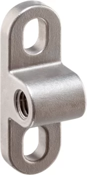
- Locators with bore hole, for spring plungers
- Locators smooth, for spring plungers
- Holders for spring plungers
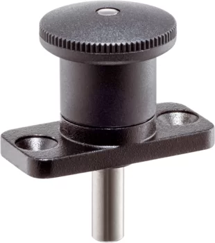
- Index Plungers Mini Indexes with mounting flange
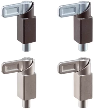
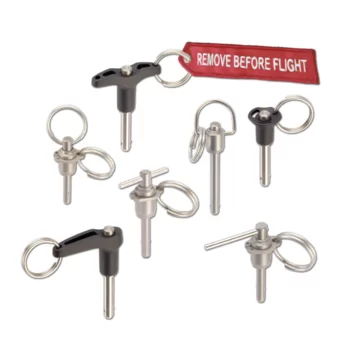
- Index Plungers with locking mechanism push-lock
- Index Bolts threadless, weldable
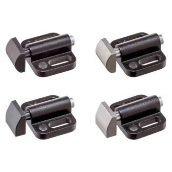
- Spring Push Plungers with mounting flange, horizontal
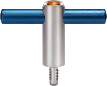
- Threaded Lifting Pins self-locking, with handle
- Bedding Supports
- Flat Knurled Nuts DIN 467
- Flat Knurled Thumb Screws DIN 653
- High Knurled Nuts DIN 466
- High Knurled Thumb Screws DIN 464
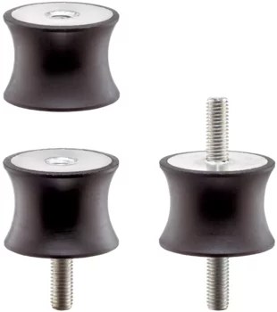
- Rubber Metal Buffers waisted
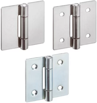
- Hinges
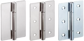
- Hinges
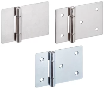
- Hinges elongated on one side
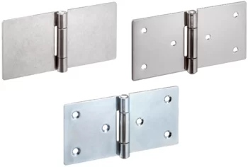
- Hinges elongated on both sides
- Hinges long version
Further Information:Product Groups- Forestry Tools
- Accessories
- Promotional Boxes
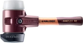
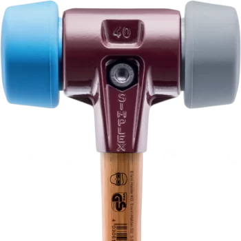
- SIMPLEX soft-face mallets, cast iron housing
- SIMPLEX soft-face mallets, reinforced cast iron housing
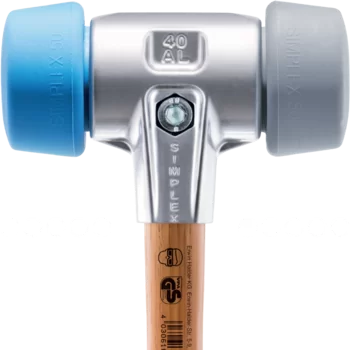
- SIMPLEX soft-face mallets, aluminium housing
- SIMPLEX soft-face mallets, cast iron housing, with "Stand-Up"
- SIMPLEX soft-face mallets, cast iron housing, 50:40
- SIMPLEX soft-face mallets, aluminium housing, 50:40
- SIMPLEX soft-face mallets, cast iron housing, extra short handle
- SIMPLEX soft-face mallets, cast iron housing, with "Stand-Up", extra short handle
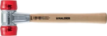
- BASEPLEX soft-face mallets
- SIMPLEX sledge hammers, cast iron housing
- SIMPLEX sledge hammers, reinforced cast iron housing
- SIMPLEX sledge hammers, cast iron housing, with "Stand-Up"
- SUPERCRAFT soft-face mallets
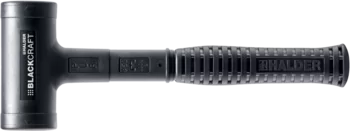
- BLACKCRAFT soft-face mallet
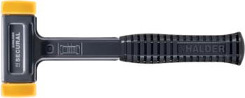
- SECURAL soft-face mallet
- SUPERCRAFT sledge hammers
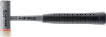
- FERROPLEX Combi Hammer
New Items- SIMPLEX soft-face mallets, 50:40 TPE-soft / TPE-mid; with cast iron housing and high-quality wooden handle
- SIMPLEX soft-face mallets, 50:40 TPE-soft / TPE-mid; with aluminium housing and high-quality wooden handle
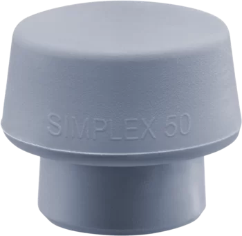
- SIMPLEX insert, 50:40 TPE-mid, grey
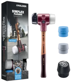
- SIMPLEX Plus Box Starter Kit SIMPLEX soft-face mallet D60, rubber composition with "stand-up" / superplastic as well as one TPE-soft and one TPE-mid insert plus bottle opener
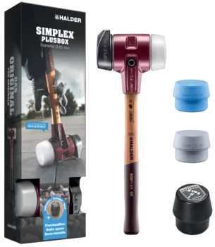
- SIMPLEX Plus Box Starter Kit SIMPLEX soft-face mallet D80, rubber composition with "stand-up" / superplastic as well as one TPE-soft and one TPE-mid insert plus bottle opener
- SIMPLEX Promotional Box Automotive SIMPLEX soft-face mallet D40, copper / soft metal plus puncher
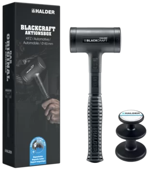
- BLACKCRAFT Promotional Box Automotive BLACKCRAFT soft-face mallet D60 plus Magnetic Holder
- Promotional Box Dreamteam Door and Window Construction SIMPLEX soft-face mallet 50:40, TPE-soft / TPE-mid and SECURAL plus soft-face mallet
- Service
- Newsroom
- Company
- Contact
23310.0086 - Down-Thrust Clamps
moveable, size 40
The moveable down-thrust clamps are used, amongst other things, when swivel movements are not possible because of the workpiece.
The clamps have the following advantages:
- Easier and quicker workpiece change by moving the clamping claws forwards or backwards.
- The clamping range in horizontal direction is between l1 min. and l1 max..
- To change the workpiece, the clamping claw can be pushed back from l1 max. by dimension l2.
- Rapid manual clamping by means of the clamping screw, the adjustable clamping lever, or the double eccentric tension lever.
- As with all down-thrust clamps, the clamping claw of this version can also be swivelled away to the left or right. The use of positioning ring 23310.0350 allows the clamping position to be fixed. Here h1 min. increases by at least 7 mm (stroke minus 7 mm).
- Compact design, therefore less space requirement when clamping.
- Easily adjustable even to large clamping heights, using the height adjusting cylinders.
As the force applied by the operator is not known for the versions with levers, the clamping force is given in the tables as a guide value. The average value was determined by tests.
This article 23310.0086 - Down-Thrust Clamps moveable, size 40 / with adjustable clamping lever with axial bearing (d1: 40 mm) is one variant of the article group Down-Thrust Clamps moveable, size 40 (EH 23310.)

- with adjustable clamping lever with axial bearing – picture 1
- d1: 40 mm
- b1: 30 mm
- b2: 13 mm
- d2: M12
- h1: 88 mm – 118 mm
- h2: 113 mm – 143 mm
- h3: 15 mm
- h4: 20 mm
- h5: 82 mm
- l1: 38 mm – 55 mm
- l2: 30 mm
- l3: 90 mm – 107 mm
- l4: 108 mm
- Stroke: 30 mm
- Clamping force1): 6 kN
- Weight: 1560 g

Material
Clamp
- Case-hardened steel, case-hardened, blackened and ground
Tension lever
- Zinc die-cast, plastic coated, orange similar to RAL 2004, matt structure
References
The clamping height can be increased by using height adjusting cylinders EH 23310. and disks EH 1107. and EH 1108. It can be reduced by employing clamping inserts, e.g. EH 22730.
Assembly
Down-thrust clamps can be attached in two ways:
- in a T-slot, using a nut for T-slots DIN 508 (EH 23010.)
- with the set screw directly in the mounting plate of, for example, a fixture
The cylinder must make contact over the whole surface.
Operation
- Push clamping claw backwards.
- Insert workpiece.
- Push clamping claw forwards.
- Adjust clamping position of clamping claw using the knurled screw.
- Secure / lock the clamping position using the knurled nut.
RoHS compliant
Contains lead - compliant according to exceptions 6a / 6b / 6c.
Contains SVHC substances >0,1% w/w
Contains lead - SVHC list [REACH] as of 27.06.2024.
Contains Proposition 65 substances

Lead can cause cancer and reproductive harm from exposure
https://www.P65Warnings.ca.gov/
Free from Conflict Minerals
This product does not contain any substances designated as "conflict minerals" such as tantalum, tin, gold or tungsten from the Democratic Republic of Congo or adjacent countries.
Contacts
Contact Standard Parts Contact Workholding Systems Contact Aviation Products RepresentativeContact Form
Information Material
Information material Standard Parts Information material Workholding Systems Information material Aviation ProductsNews
Have a look to our current new parts:
Threaded Lifting Pins with handle Bedding Supports Spring Push Plungers Accessories for spring plungers Index Plungers / Index Bolts Damping Elements Hinges Knurled Nuts / Knurled Thumb Screws